本文介绍了如何在nRF Connect SDK下配置和使用GPIO。
内容包括以下三个部分:
- 使用Zephyr GPIO API配置和使用GPIO
- DK Buttons and LEDs Library
- PPI TRACE
1. 使用Zephyr GPIO API配置和使用GPIO
nRF Connect SDK是基于Zephyr操作系统的,因此可以使用Zephyr的GPIO API来配置和使用GPIO。
使用Zephyr GPIO API包括以下步骤:
- Config中加入CONFIG_GPIO=y
- 在device tree中添加GPIO节点
- 在应用程序中获取GPIO Device
- 配置GPIO
- 读写GPIO,其中GPIO读取可以使用Polling模式和中断模式。
1.1 GPIO device的添加和获取
以下是在Device Tree中添加GPIO节点的例子,在节点中配置了两个GPIO,每个GPIO有三个参数。第一个GPIO为GPIO0.1,低电平有效;第二个GPIO为GPIO1.2,低电平有效。
n: node {

  foo-gpios = <&gpio0 1 GPIO_ACTIVE_LOW>,
              <&gpio1 2 GPIO_ACTIVE_LOW>;

}
接下来我们可以使用gpio_dt_spec来获取device tree中定义的GPIO。
gpio_dt_spec结构体包括以下三部分,分别对应device tree中GPIO的三个参数。
- port:GPIO 端口设备指针
- pin:GPIO的PIN NUM
- dt_flags:gpio在device tree中定义的配置 flags。这些flags在 <zephyr/dt-bindings/gpio/gpio.h>中定义。包括
- GPIO_ACTIVE_HIGH
- GPIO_ACTIVE_LOW
- GPIO_PULL_UP
- GPIO_PULL_DOWN
- GPIO_OPEN_DRAIN
- GPIO_OPEN_SOURCE 等。
gpio_dt_spec可以通过以下宏由device tree在具有gpio属性的节点中获取
- GPIO_DT_SPEC_GET_BY_IDX
- GPIO_DT_SPEC_GET_BY_IDX_OR
- GPIO_DT_SPEC_GET
- GPIO_DT_SPEC_GET_OR
其中GPIO_DT_SPEC_GET,GPIO_DT_SPEC_GET_OR是获取节点GPIO列表中的第一个GPIO(index=0)的gpio_dt_spec;而GPIO_DT_SPEC_GET_BY_IDX,GPIO_DT_SPEC_GET_BY_IDX_OR则是获取节点GPIO列表里指定index的gpio_dt_spec。相对于GPIO_DT_SPEC_GET_BY_IDX,GPIO_DT_SPEC_GET,在使用GPIO_DT_SPEC_GET_BY_IDX_OR,GPIO_DT_SPEC_GET_OR时,如果在device tree中找不到对应gpio的属性则将gpio_dt_spec赋值为一个指定的默认值。
下面的例子展示了如何在上面提到的node节点中获取第二个GPIO(index=1)的gpio_dt_spec。
const struct gpio_dt_spec spec = GPIO_DT_SPEC_GET_BY_IDX(DT_NODELABEL(n), foo_gpios, 1);
相当于给gpio_dt_spec初始化为以下值
{

  .port = DEVICE_DT_GET(DT_NODELABEL(gpio1)),
  .pin = 2,
  .dt_flags = GPIO_ACTIVE_LOW

}
1.2 GPIO的配置
除了gpio_dt_spec中定义的配置flags以外,GPIO还需要其他额外的配置。可以通过以下API来对GPIO进行配置:
gpio_pin_configure_dt(const struct gpio_dt_spec spec gpio_flags_t extra_flags) 相当于
gpio_pin_configure(spec->port, spec->pin, spec->dt_flags | extra_flags);
以下是一些GPIO的配置选项:
- GPIO_INPUT:将引脚配置为输入。
- GPIO_OUTPUT:将引脚配置为输出,不更改输出状态。
- GPIO_DISCONNECTED:禁用输入和输出引脚。
- GPIO_OUTPUT_LOW:将GPIO引脚配置为输出并将其初始化为低状态。
- GPIO_OUTPUT_HIGH:将GPIO引脚配置为输出并将其初始化为高状态。
- GPIO_OUTPUT_INACTIVE:将GPIO引脚配置为输出并将其初始化为逻辑0。
- GPIO_OUTPUT_ACTIVE:将GPIO引脚配置为输出并将其初始化为逻辑1
另外还有一些配置选项是Nordic独有的,比如Drive strength(bit8,bit9),它通常与GPIO_OPEN_DRAIN,GPIO_OPEN_SOURCE配合使用。具体代码如下:
static int get_drive(gpio_flags_t flags,
            nrf_gpio_pin_drive_t *drive)

{
  switch (flags & (NRF_GPIO_DRIVE_MSK | GPIO_OPEN_DRAIN)) {
  case NRF_GPIO_DRIVE_S0S1:
    *drive = NRF_GPIO_PIN_S0S1;
    break;
  case NRF_GPIO_DRIVE_S0H1:
    *drive = NRF_GPIO_PIN_S0H1;
    break;
  case NRF_GPIO_DRIVE_H0S1:
    *drive = NRF_GPIO_PIN_H0S1;
    break;
  case NRF_GPIO_DRIVE_H0H1:
    *drive = NRF_GPIO_PIN_H0H1;
    break;
  case NRF_GPIO_DRIVE_S0 | GPIO_OPEN_DRAIN:
    *drive = NRF_GPIO_PIN_S0D1;
    break;
  case NRF_GPIO_DRIVE_H0 | GPIO_OPEN_DRAIN:
    *drive = NRF_GPIO_PIN_H0D1;
    break;
  case NRF_GPIO_DRIVE_S1 | GPIO_OPEN_SOURCE:
    *drive = NRF_GPIO_PIN_D0S1;
    break;
  case NRF_GPIO_DRIVE_H1 | GPIO_OPEN_SOURCE:
    *drive = NRF_GPIO_PIN_D0H1;
    break;
  default:
    return -EINVAL;
  }
  return 0;
}
gpio_pin_interrupt_configure_dt(const struct gpio_dt_spec *spec, gpio_flags_t flags) 可以将中断配置到指定GPIO。
- GPIO_INT_DISABLE:禁用GPIO引脚中断。
- GPIO_INT_EDGE_RISING:将GPIO中断配置为在引脚上升沿触发并启用它。
- GPIO_INT_EDGE_FALLING:将GPIO中断配置为在引脚下降沿触发并启用它。
- GPIO_INT_EDGE_BOTH:将GPIO中断配置为在引脚上升或下降沿触发并启用它。
- GPIO_INT_LEVEL_LOW:将GPIO中断配置为在物理电平低时触发并启用它。
- GPIO_INT_LEVEL_HIGH:将GPIO中断配置为在物理电平高时触发并启用它。
- GPIO_INT_EDGE_TO_INACTIVE:将GPIO中断配置为在状态更改到逻辑0时触发并启用它。
- GPIO_INT_EDGE_TO_ACTIVE:将GPIO中断配置为在状态更改到逻辑1时触发并启用它。
- GPIO_INT_LEVEL_INACTIVE:将GPIO中断配置为在逻辑电平0时触发并启用它。
- GPIO_INT_LEVEL_ACTIVE:将GPIO中断配置为在逻辑电平1时触发并启用它
1.3 Polling模式下读写GPIO
可以使用以下API对GPIO进行读写操作。
- static inline int gpio_pin_set_dt(const struct gpio_dt_spec *spec, int value) 相当于 gpio_pin_set(spec->port, spec->pin, value);
对指定输出引脚设置逻辑电平。
- static inline int gpio_pin_set_raw(const struct device *port, gpio_pin_t pin, int value)
对指定输出引脚设置物理电平。
- static inline int gpio_pin_toggle_dt(const struct gpio_dt_spec *spec) 相当于 gpio_pin_toggle(spec->port, spec->pin)
翻转指定输出引脚电平
- static inline int gpio_pin_get_dt(const struct gpio_dt_spec *spec)相当于 gpio_pin_get(spec->port, spec->pin)
读取指定输入引脚逻辑电平。
- static inline int gpio_pin_get_raw(const struct device *port, gpio_pin_t pin)
读取指定输入引脚物理电平。
另外,还可以使用gpio_port_XXXX API对GPIO端口进行操作。
1.4 中断模式读取GPIO
中断模式读取GPIO包括以下步骤:
- 使用下面API给指定PIN配置中断触发方式
static inline int gpio_pin_interrupt_configure_dt(const struct gpio_dt_spec *spec, gpio_flags_t flags)
相当于
gpio_pin_interrupt_configure(spec->port, spec->pin, flags);
示例代码如下
gpio_pin_interrupt_configure_dt(&gpio_spec, GPIO_INT_EDGE_TO_ACTIVE);
- 定义回调函数,比如 void pin_isr(const struct device *dev, struct gpio_callback *cb, gpio_port_pins_t pins);
这个回调函数会在中断触发时调用。
- 定义数据类型为 struct gpio_callback的变量,这个变量保存了pin num和回调函数的信息。下面是个示例
static struct gpio_callback pin_cb_data;
- 使用gpio_init_callback()初始化gpio_callback变量,下面是一个示例
gpio_init_callback(& pin_cb_data,pin_isr,BIT(gpio_spec.pin));
- 使用gpio_add_callback()添加callback, 示例代码如下:
gpio_add_callback(gpio_spec.port, & pin_cb_data);
1.5 Zephyr GPIO API的实现
Zephyr gpio API最终会调用到nrfx gpiote, nrfx gpio驱动。它是由文件gpio_nrf.c以及头文件gpio.h里的内联函数实现的。下面以gpio_pin_interrupt_configure_dt()为例说明这个函数是如何实现的。
在gpio.h定义了内联函数gpio_pin_interrupt_configure_dt();
里面调用的函数关系如下
gpio_pin_interrupt_configure_dt() =>
gpio_pin_interrupt_configure() =>
z_impl_gpio_pnrfxin_interrupt_configure() =>
api->pin_interrupt_configure()); 也就是 gpio_nrfx_pin_interrupt_configure()
而gpio_nrfx_pin_interrupt_configure()会调用nrfx gpiote, nrf gpio的驱动。
因为大部分函数都是内联函数,所以实际使用中只多增加了一个调用层级。
接下来,我们看一下gpio_nrfx_pin_interrupt_configure()是如何实现的。
static int gpio_nrfx_pin_interrupt_configure
(const struct device *port,
gpio_pin_t pin,
enum gpio_int_mode mode,
enum gpio_int_trig trig)
{
uint32_t abs_pin = NRF_GPIO_PIN_MAP(
get_port_cfg(port)->port_num, pin);
nrfx_err_t err;
uint8_t ch;
if (mode == GPIO_INT_MODE_DISABLED) {
nrfx_gpiote_trigger_disable(abs_pin);
return 0;
}
nrfx_gpiote_trigger_config_t trigger_config = {
.trigger = get_trigger(mode, trig),
};
if (!(BIT(pin) & get_port_cfg(port)->edge_sense) &&
(mode == GPIO_INT_MODE_EDGE) &&
(nrf_gpio_pin_dir_get(abs_pin) == NRF_GPIO_PIN_DIR_INPUT)) {
err = nrfx_gpiote_channel_get(abs_pin, &ch);
if (err == NRFX_ERROR_INVALID_PARAM) {
err = nrfx_gpiote_channel_alloc(&ch);
if (err != NRFX_SUCCESS) {
return -ENOMEM;
}
}
trigger_config.p_in_channel = &ch;
}
err = nrfx_gpiote_input_configure(abs_pin, NULL, &trigger_config, NULL);
if (err != NRFX_SUCCESS) {
return -EINVAL;
}
nrfx_gpiote_trigger_enable(abs_pin, true);
return 0;
}
1.6 Zephyr中GPIO的例子
Zephyr中关于GPIO有Blinky和Button两个例子。
下面是Blinky的例子,位于zephyr\samples\basic\blinky
int main(void)
{
int ret;
if (!gpio_is_ready_dt(&led)) {
return 0;
}
ret = gpio_pin_configure_dt(&led, GPIO_OUTPUT_ACTIVE);
if (ret < 0) {
return 0;
}
while (1) {
ret = gpio_pin_toggle_dt(&led);
if (ret < 0) {
return 0;
}
k_msleep(SLEEP_TIME_MS);
}
return 0;
}
Button例子代码如下,位于zephyr\samples\basic\button
static const struct gpio_dt_spec button = GPIO_DT_SPEC_GET_OR(SW0_NODE, gpios,{0});
static struct gpio_callback button_cb_data;
static struct gpio_dt_spec led = GPIO_DT_SPEC_GET_OR(DT_ALIAS(led0), gpios, {0});
void button_pressed(const struct device *dev, struct gpio_callback *cb,uint32_t pins)
{
printk("Button pressed at %" PRIu32 "\n", k_cycle_get_32());
}
int main(void)
{
int ret;
if (!gpio_is_ready_dt(&button)) {
printk("Error: button device %s is not ready\n",
button.port->name);
return 0;
}
ret = gpio_pin_configure_dt(&button, GPIO_INPUT);
if (ret != 0) {
printk("Error %d: failed to configure %s pin %d\n",
ret, button.port->name, button.pin);
return 0;
}
ret = gpio_pin_interrupt_configure_dt(&button, GPIO_INT_EDGE_TO_ACTIVE);
if (ret != 0) {
printk("Error %d: failed to configure interrupt on %s pin %d\n",
ret, button.port->name, button.pin);
return 0;
}
gpio_init_callback(&button_cb_data, button_pressed, BIT(button.pin));
gpio_add_callback(button.port, &button_cb_data);
printk("Set up button at %s pin %d\n", button.port->name, button.pin);
if (led.port && !device_is_ready(led.port)) {
printk("Error %d: LED device %s is not ready; ignoring it\n",
ret, led.port->name);
led.port = NULL;
}
if (led.port) {
ret = gpio_pin_configure_dt(&led, GPIO_OUTPUT);
if (ret != 0) {
printk("Error %d: failed to configure LED device %s pin %d\n",
ret, led.port->name, led.pin);
led.port = NULL;
} else {
printk("Set up LED at %s pin %d\n", led.port->name, led.pin);
}
}
printk("Press the button\n");
if (led.port) {
while (1) {
int val = gpio_pin_get_dt(&button);
if (val >= 0) {
gpio_pin_set_dt(&led, val);
}
k_msleep(SLEEP_TIME_MS);
}
}
return 0;
}
2. DK Buttons and LEDs Library
DK Buttons and LEDs Library是Nordic提供的用于与按键和LED交互的模块。它是在Zephyr GPIO API之上实现的API。
- 支持读取4个以内的按键或者控制4个以内的LEDs
- 支持按键防抖功能。相对于直接调用Zephyr GPIO API, 不需要用户额外实现按键防抖功能。
- 相对于Zephyr GPIO API,调用更加简单方便。
2.1 DK Buttons and LEDs Library的使用方法如下:
- 在proj conf中加入CONFIG_DK_LIB=y。
- 在device tree中加入LEDs和Buttons的节点。
- 在应用程序中添加代码:#include <dk_buttons_and_leds.h>
- 调用dk_leds_init(), 接下来就可以设置单个LED的值或者将他们通过掩码设置到指定的状态。
- 调用dk_buttons_init(),在初始化时可以传递回调函数,当每次按键更改时都会调用此回调函数。也可以通过polling模式读取按键的值。
2.2 LEDs和Buttons设备树节点的定义
LEDs和Buttons的节点Binddings定义在
- ../bindings/gpio/gpio-leds.yaml 和
- ../bindings/gpio/gpio-keys.yaml。
Leds节点的例子如下
{
leds {
compatible = "gpio-leds";
led_0 {
gpios = < &gpio0 13 GPIO_ACTIVE_HIGH >;
label = "LED 0";
};
led_1 {
gpios = < &gpio0 14 GPIO_ACTIVE_LOW >;
label = "LED 1";
};
led_2 {
gpios = < &gpio1 0 GPIO_ACTIVE_LOW >;
label = "LED 2";
};
led_3 {
gpios = < &gpio1 1 GPIO_ACTIVE_HIGH >;
label = "LED 3";
};
};
};
这个例子中定义了四个LED。LED_0和LED_3为高电平点亮;LED_1和LED_2低电平点亮。
以下为Buttons的例子:
{
buttons {
compatible = "gpio-keys";
button0: button_0 {
gpios = <&gpio0 11 (GPIO_PULL_UP | GPIO_ACTIVE_LOW)>;
label = "Button 0";
};
button1: button_1 {
gpios = <&gpio0 12 (GPIO_PULL_DOWN | GPIO_ACTIVE_HIGH)>;
label = "Button 1";
};
button2: button_2 {
gpios = <&gpio1 12 (GPIO_PULL_UP | GPIO_ACTIVE_LOW)>;
label = "Button 2";
};
button3: button_3 {
gpios = <&gpio1 15 GPIO_ACTIVE_LOW>;
label = "Button 3";
};
};
};
在这个例子中定义了四个Buttons。Button0,Button2,Button3按键按下去时为低电平并且Button0和Button2配置为内部上拉,Button1按键按下去时为高电平且配置为内部下拉。
2.3 LEDs控制
LEDs控制的API包括以下
- int dk_leds_init(void) : 初始化LEDs library
- int dk_set_led_on(uint8_t led_idx : 打开单个LED
- int dk_set_led_off(uint8_t led_idx) : 关闭单个LED
- int dk_set_led(uint8_t led_idx, uint32_t val) :打开或者关闭单个LED
- int dk_set_leds(uint32_t leds) :通过LEDs的掩码来设置LEDs
- int dk_set_leds_state(uint32_t leds_on_mask, uint32_t leds_off_mask) :通过LEDs on/off掩码来设置LEDs状态
2.4 Buttons读取
DK Buttons and LEDs Library 为Buttons的读取提供了以下API
- int dk_buttons_init(button_handler_t button_handler):初始化Buttons并传入回调函数,回调函数在按键状态发生改变时调用。
typedef void (*button_handler_t)(uint32_t button_state, uint32_t has_changed)
button_state: 按键的状态掩码值
has_changed: 指示哪些按键状态发生了改变
- uint32_t dk_get_buttons(void):读取按键的掩码
- void dk_read_buttons(uint32_t *button_state, uint32_t *has_changed):读取按键的状态和状态改变的按键掩码值
2.5 Buttons读取实现过程
DK Buttons and LEDs Library是在文件dk_buttons_leds.c中实现的,下面重点介绍下Buttons读取的实现过程。
- Buttons lib采用中断和扫描相结合的方式。
- Buttons lib有两种状态
STATE_WAITING:等待按键中断触发事件
STATE_SCANNING :关闭中断,启动可延迟的工作队列进行定时扫描,扫描由 buttons_scan_fn(struct k_work *work)实现,默认扫描间隔为10ms。
当Buttons初始化时或者Button中断被触发时会关闭中断并启动可延迟的工作队进行定时扫描。
在扫描状态下,当发现按键状态发生改变时,调用用户回调函数;当按键掩码值为0时,即所有按键都处于release状态,程序退出扫描状态并启动中断进入等待状态;当按键掩码值不为0时,继续启动可延迟的工作队列,过一段时间进行下一次扫描。
- 因为按键采用定时扫描,所以过滤掉了按键抖动。
- 在没有按键发生时,程序处于等待状态进入睡眠,从而降低了功耗。
- 中断通常采用电平触发模式,使用PORT EVT。
2.6 配置选项
DK Buttons and LEDs Library包括以下配置选项
-
menuconfig DK_LIBRARY
bool "Button and LED Library for Nordic DKs"
select GPIO
开启DK_LIBRARY
-
config DK_LIBRARY_BUTTON_SCAN_INTERVAL
int "Scanning interval of buttons in milliseconds"
default 10
按健的扫描间隔(毫秒)
-
config DK_LIBRARY_DYNAMIC_BUTTON_HANDLERS
bool "Enable the runtime assignable button handler API"
default y
除了传递给 dk_buttons_init 的按健处理程序函数之外,还可以在运行时添加和删除任意数量的按健处理程序。使用的API如下:
-
void dk_button_handler_add(struct button_handler *handler)添加回调函数;
-
int dk_button_handler_remove(struct button_handler *handler)动态删除回调函数。
2.7 Peripheral LBS Sample
接下来,我们以Peripheral LBS Sample为例说明这个例子是如何使用DK Buttons and LEDs Library的。这个例子位于nrf\samples\bluetooth\peripheral_lbs
以下是这个例子中初始化LEDs和Buttons的代码。
初始化LEDs:
err = dk_leds_init();
if (err) {
 printk("LEDs init failed (err %d)\n", err);
 return 0;
}

err = init_button();
if (err) {
 printk("Button init failed (err %d)\n", err);
 return 0;
}
初始化Buttons:
{
  int err;

  err = dk_buttons_init(button_changed);
    if (err) {
      printk("Cannot init buttons (err: %d)\n", err);
    }

  return err;
}
接下来是LEDs的控制
BLE连接时,点亮连接指示灯:
dk_set_led_on(CON_STATUS_LED);
BLE断开时,关闭连接指示灯:
dk_set_led_off(CON_STATUS_LED);
app_led_cb():根据BLE传入命令设置用户灯状态:
static void app_led_cb(bool led_state)
{
  dk_set_led(USER_LED, led_state);
}
在main()主函数里闪烁运行状态灯:
for (;;) {
  dk_set_led(RUN_STATUS_LED, (++blink_status) % 2);
  k_sleep(K_MSEC(RUN_LED_BLINK_INTERVAL));
最后是按键的回调函数,当按键状态发生改变时,通过BLE把按键状态发送出去:
static void button_changed(uint32_t button_state, uint32_t has_changed)
{
  if (has_changed & USER_BUTTON) {
    uint32_t user_button_state = button_state & USER_BUTTON;

    bt_lbs_send_button_state(user_button_state);
    app_button_state = user_button_state ? true : false;
  }
}
3. PPI TRACE
Nordic除了提供DK Buttons and LEDs Library这个与GPIO相关模块以外,还提供了PPI trace。
- PPI trace是使用GPIO跟踪硬件事件的软件模块。
- 因为 PPI 用于将事件与 GPIOTE 中的任务连接起来,所以跟踪是在没有 CPU 干预的情况下进行的,非常适用于DEBUG。
- PPI trace 可用于跟踪单个事件或一对互补事件。
- 当跟踪单个事件时,事件的每次发生都会切换引脚的状态(请参见 ppi_trace_config())。
- 当跟踪一对互补事件时(例如,传输的开始和结束),当其中一个事件发生时,引脚被设置为1,而当另一个事件发生时,引脚被清除(请参见 ppi_trace_pair_config())
需要注意的是,这个模块并没有调用Zephyr GPIO API,而是直接调用了nrfx gpiote的驱动。这是因为这样不但效率更高而且可以实现更加丰富的功能。
关于nrfx gpiote以及nrfx gpio的API请参阅以下在线文档
3.1 PPI trace API
PPI trace 提供了以下四个API:
- void *ppi_trace_config(uint32_t pin, uint32_t evt) :配置 PPI trace 引脚以跟踪单个事件
- void *ppi_trace_pair_config(uint32_t pin, uint32_t start_evt, uint32_t stop_evt) :配置 PPI trace 引脚以跟踪一对互补事件
- void ppi_trace_enable(void *handle) :启用 PPI trace 引脚
- void ppi_trace_disable(void *handle):禁用 PPI trace 引脚
3.2 PPI trace API的实现
PPI trace API是在nrfx gpiote和nrfx ppi驱动之上实现的API,下面以ppi_trace_config() 为例看一下它是如何实现的。
void *ppi_trace_config(uint32_t pin, uint32_t evt)
{
int err;
uint32_t task;
int gpiote_ch;
nrf_gpiote_task_t task_id;
uint8_t ppi_ch;
err = ppi_alloc(&ppi_ch, evt);
if (err != NRFX_SUCCESS) {
LOG_ERR("Failed to allocate PPI channel.");
return NULL;
}
gpiote_ch = gpiote_channel_alloc(pin);
if (gpiote_ch < 0) {
LOG_ERR("Failed to allocate GPIOTE channel.");
return NULL;
}
task_id = offsetof(NRF_GPIOTE_Type, TASKS_OUT[gpiote_ch]);
task = nrf_gpiote_task_address_get(NRF_GPIOTE, task_id);
ppi_assign(ppi_ch, evt, task);
return HANDLE_ENCODE(ppi_ch);
}
static int gpiote_channel_alloc(uint32_t pin)
{
uint8_t channel;
if (nrfx_gpiote_channel_alloc(&channel) != NRFX_SUCCESS) {
return -1;
}
nrf_gpiote_task_configure(NRF_GPIOTE, channel, pin,
NRF_GPIOTE_POLARITY_TOGGLE,
NRF_GPIOTE_INITIAL_VALUE_LOW);
nrf_gpiote_task_enable(NRF_GPIOTE, channel);
return channel;
}
3.3 PPI trace Sample
在nRF Connect SDK中,Nordic还提供了PPI trace的例子,这个例子位于nrf\samples\debug\ppi_trace。
此sample中使用了四个PIN来trace以下事件。
ppi_trace_pin_setup(CONFIG_PPI_TRACE_PIN_RTC_COMPARE_EVT,
    nrf_rtc_event_address_get(RTC, NRF_RTC_EVENT_COMPARE_0));
ppi_trace_pin_setup(CONFIG_PPI_TRACE_PIN_RTC_TICK_EVT,
    nrf_rtc_event_address_get(RTC, NRF_RTC_EVENT_TICK));
ppi_trace_pin_setup(CONFIG_PPI_TRACE_PIN_LFCLOCK_STARTED_EVT,
    nrf_clock_event_address_get(NRF_CLOCK,
        NRF_CLOCK_EVENT_LFCLKSTARTED));
- 在蓝牙广播中Radio active 事件(radio ready和radio disable互补事件)
start_evt = nrf_radio_event_address_get(NRF_RADIO,
    NRF_RADIO_EVENT_READY);
stop_evt = nrf_radio_event_address_get(NRF_RADIO,
    NRF_RADIO_EVENT_DISABLED);
handle = ppi_trace_pair_config(CONFIG_PPI_TRACE_PIN_RADIO_ACTIVE,
    start_evt, stop_evt);
例子中使用了Zephyr’s链路层而不是SoftDevice链路层,这是因为SoftDevice链路层在初始化期间被阻塞,直到低频晶振启动并且时钟稳定。因此,SoftDevice 链路层不能用于显示引脚上的LFCLK开始事件。
接下来我们选择nRF52840 DK编译这个例子。四个PIN的默认定义在Kconfig中,分别为
- PPI_TRACE_PIN_RTC_COMPARE_EVT => 3 即A0.3。
- PPI_TRACE_PIN_RTC_TICK_EVT => 4 即A0.4。
- PPI_TRACE_PIN_LFCLOCK_STARTED_EVT => 28 即A0.28。
- PPI_TRACE_PIN_RADIO_ACTIVE =>29 即A0.29。
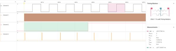
接下来我们把这四个管脚接入逻辑分析仪,打开nRF52840DK并捕获到以下波形。
通道0对应RTC 比较事件,通道1对应RTC Tick时间, 通道2对应低频时钟 (LFCLK) 开始事件,通道3对应Radio active 事件。从中我们可以看到RTC比较事件约50ms触发一次,打开PPI trace后377ms左右低频时钟被触发。大约每隔100ms 会有一组Radio Active事件。
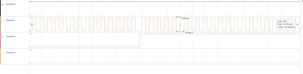
下面的图是放大的低频时钟被触发前后的波形,通道2低电平时RTC使用内部RC振荡器,高电平时使用外部低频晶振。我们可以看到RTC tick事件频率大约为32768Hz。
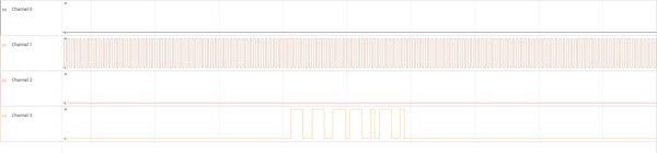
接下来的图形是放大的Radio Active事件,该事件在通道3中,高电平时表示Radio Active(Radio Ready EVT开始-->Radio Disable EVT结束)。
总结
nRF Connect SDK下可以使用以下三种方法对GPIO进行配置和使用。
- 使用 DK Buttons and LEDs Library。这种方法最简单易用。
- 使用Zephyr GPIO API。这种方法调用标准的Zephyr GPIO驱动,因此对于基于Zephyr的工程易于移植和维护。
- 直接调用nrfx gpiote, nrfx gpio 驱动。无论使用方法1还是方法2最终都会调用到nrfx gpiote, nrfx gpio 驱动。因此用户直接调用nrfx gpiote, nrfx gpio 驱动效率最高,也最灵活,比如ppi trace模块就是直接调用nrfx gpiote的驱动。如果用户已有nrf5 sdk基于nrfx gtiote,nrfx gpio驱动的程序,可以使用这种方法快速移植到nRF Connect SDK上面来。
观看网络研讨会:如何在nRF Connect SDK配置和使用GPIO